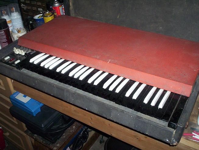
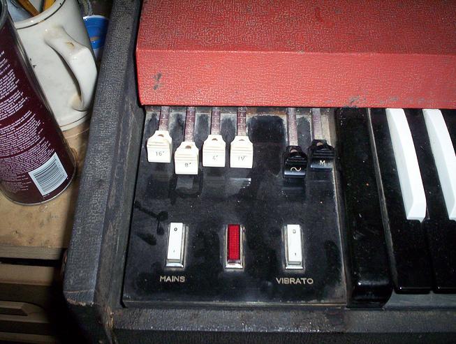
Nate's VOX Continental Organ Project
Model V-301E/2
Mfg Italy 1967
Serial#1041833
I've set up this page to chronical the repair and restoration of a VOX Continental organ model V-301E. Posting the project here will keep me motivated to complete the work and hopefully to help others who work on and repair these organs. For background info on VOX organs, visit www.combo-organ.com. If you have questions or comments, drop me an email at nate@theamericannight.com. I am located in the greater Seattle Washington area and available to repair the Vox organs (you drop off & pick up). I will also repair the vox continental or super continental tone boards for the Italian models via mail upon request. This service by mail is limited to the Italian models at this time since I have the ability to test those boards in my own organ to troubleshoot. Send me an email for details and pricing.
UPDATE! 12/1/2007 Work has begun to assemble another Italian Continental from the ground up. Click HERE to see the project come together
12/3/2006
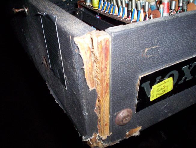
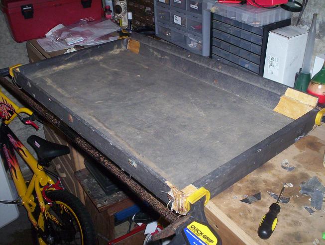
Just picked up the organ today. Total cost of project so far is $200, the price of the organ as advertised on Craigslist. I plan to keep a running tab here on this page so we can all see what the total cost to recondition this organ is. First of all, I should outline my goals for the project. I plan to restore this organ in order to play it in the band. Resale of the organ isn't a priority for me. That's not to say I may not want to sell the organ down the line sometime. But for now, this project is to restore this organ to play it.
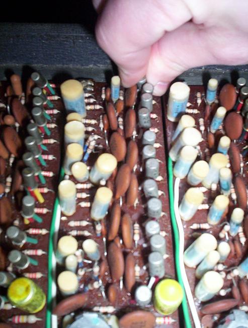
As far as these go, this Continental is in very rough shape. A cursery examination of the organ reveals that the wood cabinet itself will need some repair. It's falling apart at the joints and needs to be squared back up, braced, and glued. It looks as if the organ may have been left outside in the mud for a while. It's quite dirty. On the plus side, it's all complete. All the keys are there, all the tone boards and electronics, and YES I was excited to see every single drawbar tip is attached! The end result I'm looking for is not for the organ to be showroom perfect. That said, I'll be working to make this a fully functional and attractive piece.
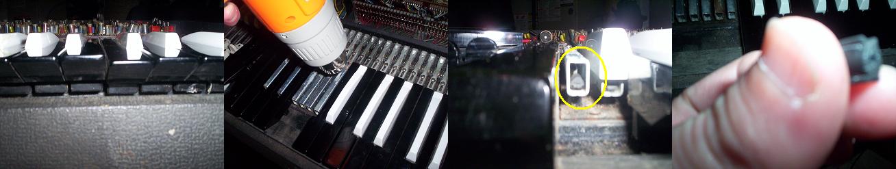
I have not yet attempted to power on the organ. First order of business will be repairing the fuse holder which is missing the cap and also to blow out all the dust and dirt inside the organ. I'll do that before trying to power it on. So without further adeu, here are some photos of how the organ looks at the start of the project.
|
|
|
12/3/2006
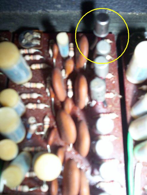
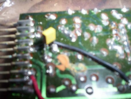
I was able to power the organ on tonight. Found that the fuse holder cap has a different thread than my Jaguar's so was not able to use the Jag fuse cap to test as I'd hoped. But was still able to power it on by pressing another fuse holder cap I had in my workbench. It didn't fit perfectly but was close enough to make the contact. I took a can of compressed air and blew out most of the dust and dirt. After powering on the organ I could hear that there are definitely dirty key contacts. Just about every key sounds bad, missing footages, warbling, some barely made sound. After spending about half an hour messing with the bias pots, I was able to get most keys to sound all footages intermittently. All of the drawbars work and the vibrato works. There is a red wire hanging off of the left side of the divider board which I haven't figured out where to solder it back on yet. Most of the bias pots look warn and like a previous owner moved them around quite a bit. Also one of the pots looks as if someone tried to fix it by placing a bead of solder on it. I anticipate replacing most or all of the bias pots. The only note at this point that sounds pretty close to how it's supposed to is the A. Dividers appear to function fine at this point. But everything sounds so bad at this point, it's hard to tell what's working properly. First order of business has got to be to brace, glue, and clamp the case. I've got to get that squared up because the keyboard is not hinging correctly. After I complete that order of business, I think the next step will be to do a really thorough job cleaning out all of the electronics and finding a replacement fuse holder cap. I think at that point, I'll be able to get a handle on where to go next with the project. Here's a shot of the hanging red wire:
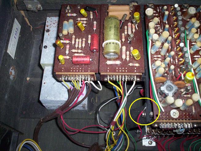
Dangling Red Wire...Where does it go?
12/4/2006
Click here to listen to an mp3 of how the organ sounds at the start of the project. I'm just playing up the keyboard starting with the low C and ending on the high C. As you can hear, she needs some serious love!
Click here to listen to an mp3 of how the organ sounds at the completion of the project. This is a studio recording of my band. The organ player is Brian Hukill.
Tracked down a replacement fuse holder cap & 1/2 amp fuse today at a local electronics shop in Bellevue called Vetco. The guy there was super nice. Fuse cap fits like a glove. Also tracked down a couple of long wood clamps that I can borrow from a friend to get this case glued back together. See photo below of back panel with new fuse holder cap. I think it's interesting that you can see the punch out for the 'BASS OUT' on the back panel. They must have used the same back panel for other Vox organs such as the Jaguar which had a BASS OUT.
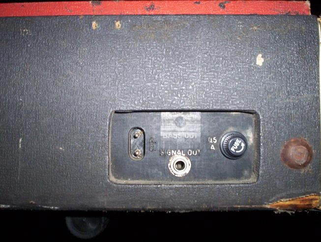
The first replacement part! New fuse holder cap...
12/5/2006
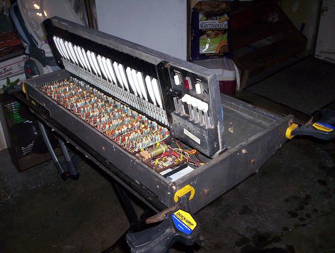
Tonight's project was to glue and clamp the case. All 4 corners of the cabinet were coming apart. Placed a generous amount of wood glue in each corner and then clamped it up. While waiting for the glue to dry, I decided to clean the key contacts with alcohol and pipe cleaners. Once was done with that, I worked on seeing how well I could tune each tone board. Many of the boards need bias pots as I surmised on day 1. One of the boards is missing a transistor. A couple barely make any tone (very low output). The C board tunes sharp (will tune to C# but not C). I made a chart as I went through each of the 12 boards. Will post that soon. It came to me tonight that I could use one of the tone boards that I know is good in order to isolate problems. For example, I could put the F tone board in the B slot and if all the B keys sound correct with all proper footages, etc (except they would be an F note, of course) then I would know that the B board is the source of the problems. I will probably attempt such troubleshooting when I am removing tone boards that need to be repaired. Meanwhile, here are some photos of tonight's work:
|
All four corners were coming apart |
The organ all glued and clamped (Thanks JD Braathen for the clamps!) |
Found a key contact broken off...not looking forward to repairing that. Looks tedious.
12/6/2006
Ordered replacement bias pots and key contact from Northcoast Music today. Here is a chart where I've gone ahead and started to keep track of what I'm finding wrong with each tone board and what I plan to try doing to fix it. I'll update this chart as I go along. I expect that in some cases, I'll end up throwing multiple components at a board before I end up with a good fix. This should be good to start. As you can see, I plan to replace quite a few of the bias pots. I went ahead and ordered a full set of 12 from Northcoast (www.northcoastmusic.com).
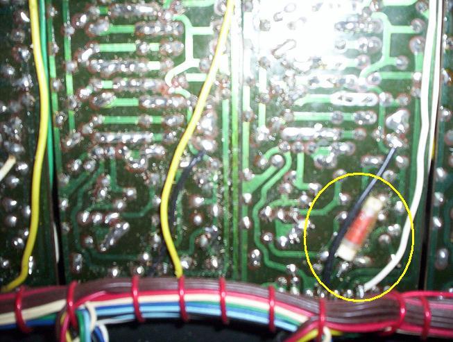
Spent some time tonight tinkering with the C tone board. It's a shame it won't tune down to C. I noticed that if you take a look at the back of the boards, some of them have a very small value capacitor soldered to the back of them such as 10000pf. The C board has a spot where it looks like one used to be glued on. You can also see the remnants of one of the leads hanging out of the solder. For fun, I held a .1 micro farad capacitor onto those two solder points to see what would happen. It caused the board to produce a VERY LOW FREQUENCY TONE. Tried a larger value cap and it caused the tone to get LOWER FREQUENCY. This is a good sign since the board is tuning sharp. I need to get it to produce a slightly lower frequency tone. So I think if I can nail down the correct value of capacitor to put back on there, I can get this board to tune down to the C as it's supposed to. I just need to bend the tone down a half step, approx. I will try a 10000pf cap like I see on one of the other boards. Tonight I also tried placing a generic PNP transistor where the missing one is on the B board. It did nothing.
|
Note |
Problem |
Work |
|
C |
OK |
Board tuned sharp. Try replacing caps near tuning coil. Placed 10000pf cap in parallel with another cap near the tuning coil. Board now tunes to C. Board tunes sharp when it's cold. After a few min of powering on the organ, board produces correct tone. Suspect leaky cap. 1/12/06 Problem was bad oscillator transistor. Replaced both oscillator transistors. Removed 10000pf cap. Board now tunes to C. Sounds great. 10/7/2008 Replaced all divider transistors with SFT-353 type. Works reliably. |
|
C# |
Had bad bias pot. Try replacing bias pot. 12/10/06 replced bias pot. Board functions normally with exception of missing 16' tones. Will try replacing the 2200pf cap near the set screw soon to see if that fixes 16'. 12/13/06 This board is not functioning normally as I'd thought. The tones are very weak in volume compared to the other notes. All footages are there but are weak. Will try replacing two PNP transistors near tuning coil with the new Raytheon Germanium PNP. 12/16/06 Found bad transistor near tuning coil. Replaced with NOS Raytheon Germanium PNP. Sounds perfect. 10/7/2008 Replaced all divider transistors with type SFT-353. Works rock solid. |
|
|
D |
OK |
|
|
D# |
OK |
Replaced bad transistor in 6th divider. |
|
E |
OK |
Try replacing bias pot. Try replacing 2200pf cap near set screw. 12/13/06 Board now appears to function normally. Will monitor this board but for now am marking OK. 12/17/06 E was sounding as if missing footages. Replaced bias pot. Sounds perfect now. 1/13/07 Found E is was missing 16' tone in low E when cold. Replaced two divider transistors closest to bias pot (lowest divider) and seems OK now. |
|
F |
OK |
1/12/07 This note started missing 16' when cold. Replaced divider transistor at the end, closest to tuning coil. Now works great. 10/13/2008 started having issues with this board again. Replaced all divider transistors with SFT-353 type. Works great. |
|
F# |
OK |
Board did have warble. Try replacing bias pot. 12/10/06 warbling on this tone seems to have worked itself out but will replace bias pot soon as precaution. |
|
G |
OK |
Was originally bad and produced no tone. Try replacing bias pot. Look for leaky caps. 12/13/06 replaced bias pot and G board now sounds very good. |
|
G# |
OK |
Try replacing bias pot. 12/16/06 This board functions normally now. |
|
A |
OK |
Try replacing bias pot. Verify that replacement transistor is correct type. 12/10/06 cross referenced AC113 transistor at www.datasheets.org.uk and verified is correct type -- PNP low power type. Also unable to reproduce warbling sound that I noticed on this note when I originally went through it. Sounds OK now. |
|
A# |
OK |
Originally had very weak tone. Try replacing bias pot. Bias pot has been tampered with. 12/10/06 replaced bias pot and replaced 2200pf cap with 10000pf (type on hand) and board now functions normally. 12/13/06 I'm not sure the original cap was 2200pf since the writing is blurred from leaky electrolytic juice! Could have originally been a 22000pf cap. Anyhow, the 10Kpf cap is working nicely. Still something wrong with this board though as it takes a minute to warm up and function normally. |
|
B |
OK |
Try replacing missing transistor & check for leaky caps. 12/10/06 replaced missing transistor, bias pot, and 100uf cap. No change in operation. 12/16/06 To date what has been replaced on this bard is all .1uf caps, 3 transistors, and the bias pot. Tried another bias pot just to rule out a defective pot. Still no change in operation. Replaced all electrolytic caps and transistors. Still bad. 1/12/07 Help from Richard Brinkerhoff. Transistors were in backwards. Removed and resoldered transistors into place correctly. Board works great now. |
|
Some boards have small capacitors soldered to the back |
The C tone board is missing that capacitor (note where it was glued on) |
12/7/2006
Last night I took inventory of what type(s) of transistors are in each tone board. Here's what we have:
C: SFT363
C#: SFT363
D: SFT363
D#: AC134 005
E: SFT363, one RCA 2N591 VFK
F: SFT363, one Sylvania 350 ECG102A
F#: SFT363, AC134 005
G: SFT363, one 2N406 VFK
G#: AC134, ATE5
A: SFT363, one Thorn AC113
A#: GE53 416, AC134
B: SFT363
I surmise that the E, F, G, and A# boards have been repaired in the past since they have one transistor of a different type than the rest on the board. Looks to me that overall, this Italian Connie was originally fitted with SFT363 and AC134 PNP type transistors. Purchased a package of 12 replacement germanium PNP type transistors for a guy on ebay today.
The best source I've found for data on old transistors is www.datasheets.org.uk where you can get spec sheets, pinouts, etc. So far have not been able to turn up info on the SFT363 but did find info on the AC134 on that website. Here's specs & pinout for the AC134. I compared the pinout on the AC134 to the SFT363 and they are the same. The transistors in this Continental almost all have the leads color coded. Another thing is that most have a red dot on the transistor to mark the emitter.
12/8/2006
Today I experimented with various value capacitors on the C board as noted above. Tried 15pf, 101pf, 1000pf and 10000pf caps. Through experimentation, found that a 10000pf (.01uf) cap produced about a half step drop in pitch on the C board (which was tuning sharp). Here's a pic of the cap soldered into place. I have had some difficulty still with the C board not holding tune (going flat). That seems to have worked itself out but we'll see if it can hold it's tune over time. For now, I've moved the C board into OK status in the chart. Note: this fix could be used to take another tone board and tune it to a lower pitch such as if one needed an A board and only had a B board, an appropriate value cap could be soldered into this spot to lower the pitch of the board so it's tunable to the desired note.
Trial And Error: A 10000uf cap replaced missing component on back of C board
12/10/2006
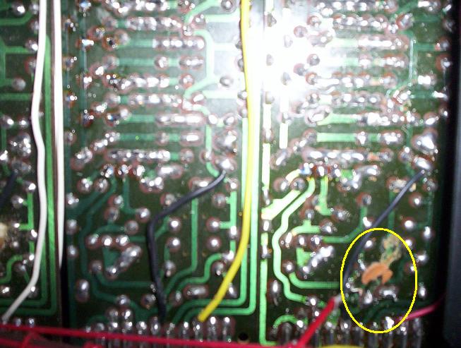
Replacement bias pots from Northcoast came in today! Made progress on the A# and C# tone boards. Both boards got new bias pots. The C# bias pot replacement went very smooth and it was easy to remove and solder in the new component. I'm still missing 16' tones on the C#, however. More on this in a moment. The A# board was a good learning experience. After removing the old bias pot, I found that the tracing on the board was coming up around where the leads were soldered in. I couldn't get the new bias pot to solder in well. I ended up soldering in some point to point jumpers (see pic below). After doing this, I was able to successfully rotate the bias pot and get a good tone out of the board. When tightening the screw back in, I accidentally brushed up against a 2200pf cap which is placed right next to the set screw. Worried that I may have damaged the cap, I took a closer look and saw that one of the leads was broken off. I don't think I did this, though since when I pressed on the cap gently, pushing the lead back into place, I miraculously got my 16' tones! At this point, I went to my selection of caps and found the closest one I had was 10000pf. I did a quick solder job, fixing it to the back of the board to test. The 16' tones sounded just like they're supposed to -- even with a different value cap. So at this point, removed the 2200pf cap and soldered the 10000pf cap in it's place (see pic). Have now moved the A# board into OK status on the chart. It occurs to me now that I could be missing the 16' tones on the C# board due to a leaky cap in the same position. Will try replacing that one to see if that does the trick.
Also spent time with the B tone board. Still no luck here. Replaced the bias pot, replaced the 100uf cap which appeared leaky, and also replaced the missing transistor with the generic silicon PNP transistors I got at Radio Shack. After doing this, the board still sounded identical to before making these repairs. There are quite a few caps on this board (and most of these boards frankly) that are suspect so will work to replace them one at a time until I get a good result. I will also replace the silicon PNP transistor with a Raytheon Germanium PNP which I have on order.
|
Note new 10000pf cap and bias pot on A# board. B board sports new bias pot, PNP transistor, and 100uf cap |
Installed new point to point jumpers (black wire) due to bad tracing on A# board. |
I'm definitely starting to see some light at the end of the tunnel. There are really only two boards right now that make the organ unplayable -- the B and G boards. The rest of the tones are either there or 'almost' all there. After looking hard at these electronics for the past week, it's a miracle at all that this organ works at all. So many of the caps look leaky -- I can tell by how they're bulging at the tops and some have turned brown from leaking electrolytic juice.
12/13/2006
Have been sick with the flu the past few days so have spent very little time on the organ project. But have received a few emails from folks offering help and suggestions. I really appreciate that. Every little bit of knowledge will help out here. Case & point, someone recommended I pick up a new soldering iron with a variable temp control to help prevent the tracings from coming up when I work on the boards (as happened when soldering the bias pot onto the A# board). Tested out the new iron tonight by replacing another transistor that I found had a broken lead. The board still isn't working but the iron worked great and no tracings came up! I spent a few minutes tonight and just for fun, I placed the A# board which is working into the slot for the B board. As I assumed, the B keys then worked just fine (except with an A# note of course). At least this isolates my problems to the B board itself. Hopefully those PNP transistors will arrive soon.
12/13/2006 EVENING
Raytheon Germanium PNP transistors came in tonight! Some good progress. Replaced the bias pot in the G board and it now functions normally. Replaced 3 transistors and 2 caps in the B board but it still does not produce a tone. I started with the 2 transistors that were damaged, obviously, and then replaced a 3rd transistor which was near the tuning coil. I figured if one of the divider transistors were causing the problem, I'd be missing a footage and not the whole tone, hence my logic for replacing the 2 transistors nearest the tuning coil first. I had .1uf caps on hand so replaced the two caps of this value also near the tuning coil. I double checked my solder connections on the bias pot I'd installed on this board. Looks OK. I took a spare transistor and touched the leads to the solder points for each of the remaining transistors I did not change out to see if I could get the board to produce a tone. No such luck which leads me to believe it's one more more bad caps at this point. Not sure what else to do besides start throwing in some caps. I will order some caps for it tomorrow. Took an inventory of the required values.
12/17/2006
We had one heck of a storm here on Thursday night with hurricane force winds. Over one million without power. Still several hundred thousand without power as of today. We were one of the lucky homes to get power back on Saturday afternoon. Now could heat the iron back up! Great news to report. All notes now function and sound perfectly with the exception of the B. Today I found a bad transistor on the C# board which I replaced with the Raytheon Germanium PNP. This was good affirmation for me that I was getting the leads correct on the transistors. The E also needed a new bias pot since it was not consistently getting all footages. It now works great. My attention will focus on ordering all replacement caps for the B board. Have looked for obvious blown resistors and bad soldering on the board. I guess one thing I have not done yet is to just lightly heat each solder joint on the board. If there's a cold joint, that might fix it. I had a cruise control amplifier for my '78 Mercedes that was fixed with that trick. Will give that a try. For now, I'm assuming I have a bad cap and will order and replace all of them. Here's a pic of the new transistor installed on the C# board.
Replaced one PNP transistor in C# board with Raytheon T59247
Priority right now is fixing the B board. After that's done, here's some of the remaining items that need work (in no particular order):
1) Retolex the organ.
2) The two threaded shafts that the rear cross braces screw into are missing. I need to find a suitable replacement.
3) Clean keyboard, drawbar assembly, switches, etc. This is cosmetic cleaning required only.
4) Level the keys. Some keys are sitting up higher/lower than others so the keyboard needs to be leveled out.
5) Oil key mechanism (planning to use a silicon based lubricant unless there are other suggestions.)
6) Glue and repair cracked F# key cover.
7) Glue and clamp the wood cover for the organ such as I did with the organ case.
8) Give a good thorough cleaning to the orange top to see how good I can get it. I'd prefer not to retolex the top if I can get it looking decent. Replace missing VOX logo on the top.
9) Replace broken key contact
10) Organ lid latches need replacement.
11) I discovered the power cord for this organ has a short in it. I'd like to find some way to repair that. Have been using the cord from my Jaguar organ.
12) Solder back on dangling red wire. I think I've figured out where this goes. It's a ground wire. There's a VERY faint background hum which goes away when the wire is touched to a nearby solder joint which I found through trial and error.
12/18/2006
Ordered all required replacement capacitors from All Electronics (www.allelectronics.com). I also ordered a couple other goodies that I found on their site including some lower cost PNP transistors, a 2N2906, which I will experiment with. The question of Germanium vs. Silicon transistors has been heavily discussed on the combo organ list and it sounds like for a divider circuit, the Silicon should function just fine and will not affect the sound of the organ. So picked up 6 of those to experiment with. I also found a bias pot which appears similar to the ones I ordered from Northcoast music except they're 10 for $1. I'll experiment with those and report back on if they're suitable. The Northcoast ones appear to be 500 ohms whereas the ones I got 10 for $1 are 300 ohms (All Electronics part# TP-300). I tested continuity on the resistors in the B board and they all appear to have continuity.
12/19/2006
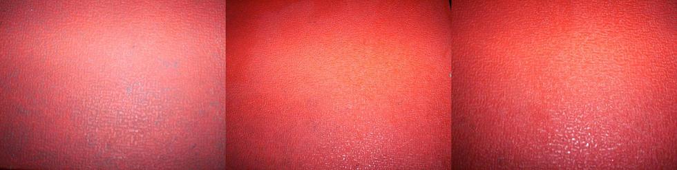
Today I decided to give a go at cleaning the orange top a bit while awaiting the capacitors from All Electronics. The orange tolex is in what can only be described as very FILTHY condition. On the positive side, it's not torn -- aside from a small spot here and there. So what I'm dealing with here is 40 years worth of dirt. Worst of all, there's patches of a black, tar-like substance on the top. Actually, it might REALLY be tar. It appears so. Here's an overhead shot of the orange top at the start of tonights bout:
The orange top was filthy and dotted with a "tar like" substance...
My first approach to cleaning the top was to get a really hot solution of water, soap, and just a drop of bleach. I used a towel to scrub all sides of the top. This steaming hot solution was great at getting off the big globs of black tar. The far left photo in the array below is the tolex at the start, before any cleaning. The second in the array is after scrubbing with the hot soap, water & bleach solution. You'll notice that it removed a lot of the dirt & tar from the ridges of the tolex. I was quick to dabble the damp tolex with paper towel in order to pick up the dirt. I used a soft bristle brush as well after scrubbing with the towel. The third photo to the right in the array is after lightly scrubbing with a stiff wire brush. I was very careful with the brush not to damage the tolex which I think would be possible with a stiff bristle. But with a gentle circular motion, I was able to get much more of the dirt out of the ridges. I'm going to pick up another stiff wire brush at the hardware store which I think will be more suitable than the one I experimented tonight. At the end of the evening, the top still isn't what I'd consider finished but I think that I definitely will be able to clean it to my satisfaction with another go at it. I plan to finish off the job with a good vinyl conditioner (once the top is as clean as I can get it).
Results after scrubbing with a hot soap, water & light bleach solution
12/20/2006
Continued to work on cleaning the orange top tonight. It's looking pretty orange! Did some more scrubbing with the hot soap & water solution and the stiff wire brush. I also took a pick and carved out some of the particularly difficult grooves where tar was caked in. Did a quick cursery cleaning of the keys and drawbars with Windex. Even without retolexing this organ, the results are pretty dramatic compared with the "before" pics from day 1. Here's the results:
|
A little TLC went a long way in cleaning up the VOX |
Closeup of the orange top (post day 2 cleaning) |
These results go to show that the tolex on these organs, even when soiled and filthy, can be cleaned with a little TLC and no fancy chemicals. The trick here was steaming hot water, soap, and just a splash of bleach (not much). Tools were a towel, a soft bristle brush, a stiff wire bristle brush, and a small pick (awl). Scrub vigorously with the towel and hot soap & water solution. Next scrub with the soft bristle brush. Finally, give it a detailed light scrub with the stiff wire brush. One thing that was a bit freaky is that when scrubbing with the stiff brush, it appears as if your staining the tolex a muddy grey color but this is just the dirt coming up from inside the grooves. The method I used was to take the top section by section with the wire brush and once I was done with a section, I would take the soft bristle brush and scrub on some of the soap & water solution and then dabble dry with a paper towel. This picked up all the dirt that was coming up from inside the grooves. I think to get these really clean, you've got to not only scrub 'em but also be mindful to frequently mop up the dirty suds. If you just let the suds sit there, the dirt will sink back in or leave a residue. There were a few grooves with the black tar that would not get clean with the wire brush so that's where I went detailed with a magnifying glass and the pick which was kind of an awl type, hole punch, type tool -- a pretty dull one. Finally, apply your favorite vinyl conditioner for shine/lustre. There may be other cleaning methods but this one worked well for me.
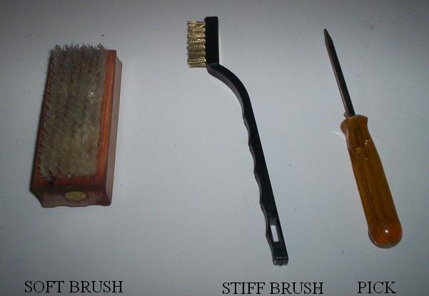
Specialized Tolex Cleaning Tools
12/26/2006
Some dissapointing news. Still struggling with that B board. Order came in from All Electronics. Replaced all electrolytic caps with same value and all transistors in the board. For transistors I used 8 Raytheon germanium PNP and 6 Motorola Silicon PNP (2N2906) from All Electronics. The two nearest the tuning coil are Raytheons. I purchased a meter which can test transistors so I tested each before placing it in the board to make sure they were working. Also replaced one resistor that looked suspect. Board still produces no tone, just a sort of white-noise-like hissing sound. There is a tone way in the background but I suspect this may be blead through from another board since it is there even when the B board is completely removed. I plan to try heating each solder joint to eliminate a bad joint as the culpret. Next thing I guess would be to replace all resistors on the board, a tedious task. If anyone has other ideas on what I should try, let me know. I did check with a magnifying glass to make sure the little wires on the tuning coil are in tact and the solder points are good on the tuning coil. Some other things I've done are test each resistor with the meter. All resistors with same color code seem to read close to the same value & have continuity. I've begun testing continuity as well between tracings on the back of the board. My opinion at this point is this is either something really simple or it's the tuning coil. This organ was in too rough a shape NOT to have at least one of the boards be shot. I may be looking for a replacement soon if I can't revive it. The C has also developed a quirk where it will be about half step sharp when I initially turn on the organ and then as the organ heats up, it will drop down to the correct pitch. Here's a closeup pic of the B board as it appears today.
B board: Lots of new parts but no improvement
12/28/2006
I took a day off from working on the oscillator board. In the mean time, have picked up the Tee Nuts I need and some wood filler (DAP plastic wood). The two holes in the back of the organ where the rear cross braces attach are missing the original Tee Nuts and are in very rough shape. I plan to use the "plastic wood" to fill the holes and sand down so I have a fresh surface on which to drill the appropriate size hole and install the 1/4" Tee Nuts. I found a Hillman Tee Nut part which is a direct replacement for the original nut. I will post the Hillman part number here. Many major hardware chains such as Ace carry a Hillman set of assorted nuts, bolts, and other parts.
Back to the B oscillator board. I plan to pick up a complete set of new resistors and ceramic disk caps at VETCO (Bellevue, WA) on the way home from work tonight. I plan to start by replacing resistors and then if that does not do the trick, I will move on to the ceramic disk caps. There are a few resistors where the values have shifted pretty far from the original. They still have continuity...but...perhaps one has shifted enough in value to foul up the entire function of the board. Hopefully I will have time tonight to try soldering in some of these parts and I'll post on how that goes. Wouldn't it be something to have a board with 100% new components (save for the tuning coil)! Well...if it works...I guess that's something.
12/29/2006
Replaced several 2.2K & 10K resistors last night & also a single 1K resistor. I targeted resistors located near the tuning coil and the bias pot. I may be imagining, but it appeared to have a positive effect. The board seems to be producing more output but still not a distinct tone. I think the tone I'm hearing is a faint sound of the harmonic from the IV voice. There is one resistor that does seems off in value which is right next to the 100uf cap which helps to drive the oscillator. It's a 220K resistor which I didn't have on hand. I'll get one of those tonight and give it a try. The local shop didn't have the 500pf and 2200pf ceramic caps that I needed so I will have to order those if the resistors don't do the trick. I also want to place an order with vintagevibe.com for some more replacement PNP transistors. They seem to have a good price on a suitable replacement.
12/30/2006
Made some good progress today on the B board. Replacing several resistors has had a negligable effect on the board as reported above so I got to thinking that perhaps the Motorola PNP transistors might not be a good replacement. I hand picked six of the leftover original SFT 363 transistors by testing them with the multimeter. The ones with really high or wildly fluctuating hfe measurements were eliminated and I went with the six which showed the most promissing hfe measurements, generally in the range between 17-25 with my meter. I will be curious to see what the new transistors read when I get them from vintagevibe.com because the Raytheons read in the high 100-300 range and the Motorolas read around 50. Anyhow, I digress. After removing the six Motorola transistors and reinserting the SFT 363s, the board now produces a distinct B tone but it seems very high pitch -- 2 octaves above where it should be. At least I know the tuning coil is working and the board does oscillate. I took some time to map out the pin designations using my meter to test. This actually helped me understand quite a bit about how the tone boards go to creating the signature sound of the organ. Here's a rundown on the pins (remember these are for the Italian boards so will probably be different on the other models). Looking at the board as if sitting in front of the keyboard, starting from the left most pin:
[1] 6th divider output
[2] 5th divider output
[3] 4th divider output
[4] 3rd divider output
[5] 2nd divider output
[6] 1st divider output
[7] Ground
[8] Master Oscilator Output
[9] Vibrato
[10] +7v DC
By using my meter, I could detect which dividers each note uses. B1 (low B) gets sound from pins 1,2,3. B2 uses 2,3,4. B3 3,4,5. B4 4,5,6. Of course, there are three footage drawbars so this makes sense. A light bulb went off for me here since I had been struggling to understand why the 6 dividers for just 4 octaves of keys. Well, as I learned here, each notes uses 3 of the dividers (one per each of 3 footages). Makes sense now. So I'm thinking some of those SFT363 transistors that I reinstalled must not be good. I wiggled one of them and started getting the hissing sound again. Wiggled it again and it went away so I think that one must have a bad lead. Am going to hold off on making any more repairs to this board until I get the new transistors from vintagevibe.com. Todays results also give me confidence in my capacitor changeouts. I used the same values as the original and what I'm hearing is pretty much in tune with the B note. Having the tone sound too high seems likely a function of one or more bad divider transistors. If a cap were off or bad, I would think that my note would sound more off the mark rather than just a higher octave of the note I want. Hope that makes sense.
A quick project tonight was to glue the cracked F# key. Here's some pics. Basically I just took a pipecleaner and some of the isopropyl alcohol to clean the key paying particular attention to the crack to get the dirt out of it (no sense in gluing in dirt). Then just applied some cement to the inside and the crack and "clamped" it with some wire ties.
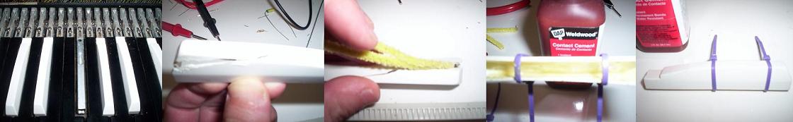
Cement applied to inside of cracked key
1/7/2007
Have been tinkering with a few things since am waiting for the transistors for the B board from Vintagevibe.com. One thing is I was having some trouble with the E where I kept having to readjust the bias pot. I exchanged email with a guy from Italy who recommended a 220ohm bias pot. The ones from Northcoast are 500ohms. So I went ahead and installed one of the 300ohm bias pots that I got from All Electronics. Was able to dial it right in. We'll see how it holds up (i.e. if I'm still having to constantly readjust the pot). I also have been trying to combat the problem with the C board where it will play sharp when cold and then tune down to the correct pitch as it warms up. I replaced all of the caps near the tuning coil (the 3 100000pf caps and one 39000pf cap). This had no effect and the problem remains. I think it's a leaky cap. If you turn the organ off, wait say 10 seconds, then hold down a C note while powering on the organ, you can actually hear the pitch shift downwards. I also replaced the 100uf cap next to the tuning coil. I've decided as part of this project, each board will have a new bias pot and a new 100uf cap as preventative maintenance. I also swapped out the 500ohm trim pot for the 300ohm on the B board but this didn't fix my problems there. Should get the vintagevibe order this week and am excited to try the new transistors on the B board.
One good thing that's come from the tinkering this week is validation that the replacement caps I've been putting into the B board ought to work just fine. I used caps from the same batch for replacement on the C board and they worked just great. The tone is exactly the same as the original even though these new caps are ceramic type, it made no difference. Also nice to know the 300ohm bias pots are a good match since they are a more economical alternative (allelectronics.com part number TP-300).
1/9/2007
Replacement transistors from vintagevibe.com came today right on time. I completely replaced all 14 transistors in the board with the new ones from vintage vibe and tested each transistor with my meter before placing it in the board...and...nothing. I then started replacing each of the resistors that go between each transistor. At this point, I've decided to change tactics from "troubleshooting" to just simply replacing EVERY component on this board. I will order the 2200pf and 500pf caps. Other than that, I have all the rest of the resistors on hand. Time to get soldering. If that doesn't fix it, I'm going to be hard pressed knowing what to do next other than keep a watchful eye on ebay for another board or try and send this one out to a tech somewhere to take a stab at it.
1/12/2007
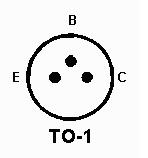
I owe a huge debt of gratutude to Richard Brinkerhoff who I met on the combo-organ discussion list. Richard was kind enough to come by last night armed with his oscilloscope and electronic wits to lend a hand with this project. In just about 3 hours we managed to get the B tone board back up and running. Taking a systematic approach, we used the scope to first get the oscilator up and running. One of the oscilator transistors was in backwards. Once we had that repaired, we could see the square wave on the scope when plugging into the main oscilator out and ground pins. Also discovered that my divider transistors were not in correctly. The correct pin order is: emitter (nearest to edge of board), collecter (middle), base (nearest center of board). After soldering in the first two divider transistors correctly we could hear (and see on the scope) the correct wave. The next divider proved a bit more challenging before finally realizing that the other divider transistors which were in backwards were causing interference. So at that point we removed ALL of the divider transistors which were incorrectly soldered in and just put them all in correctly. After a quick turn of the bias pot, the B sounded great!
Some other pointers from Richard that I'll pass on here. It's probably best not to use the ceramic capacitors for the oscilator portion of the board since those change value slightly with temperature which would cause the organ to go slightly outu of tune as it warms up. I will replace the ceramics in the B and C oscilator circuit with either new polypropeline caps or just try out some of the original caps. Ceramics will work just fine in the dividers. Also Richard found the pitch shift I am getting on the C is due to a bad oscilator transistor which I will replace. The problems with the E missing footages when cold is due to one or more bad divider transistors. I will note which divider is off when cold and replace the related transistors. Lastly, Richard was a huge help in locating where the hanging RED WIRE should go. I was correct in thinking this is a ground and we found that placing the wire onto pin 7 of the C tone board (nearest board to the wire) worked like a charm. The additional grounding just makes the organ that much cleaner sounding and the very little bit of background rumble present with the wire hanging goes away completely.
Lastly, a good tip was to try and match the divider transistors with a simpile hFE test on my meter. We chose 12 divider transistors with a similar hFE range. Since these boards have only one bias adjustment, you could run into trouble if some of the divider transistors are not close enough in property. The bias adjustment has no bearing on the oscillator transistors, however, so those do not need to be matched. For this organ, I ended up with 11 divider transistors from the batch I ordered from vintagevibe and 1 of the Raytheon transistors I ordered from the guy on ebay. The oscilator transistors are 1 from the vintagevibe batch and 1 Raytheon from the ebay batch.
This organ should be fully functional after making these final repairs and it will be time to focus on the cosmetics. Once again, a huge thanks to Richard Brinkerhoff. He definitely gets the next Connie that shows up on Seattle Craigslist!
1/12/2007
Tonight's work started with fixing the pitch shift problem on the C board. Replaced the bad transistor in the oscillator circuit that Richard found last night and also the second transistor as well as preventative maintenance. I found that once I did this, the board would not tune to a C, more like a B. So I removed the 10000pf cap that I had soldered to the back of the board last month. Perfect! C keys all sound great. Found that the F was missing 16' tones when cold and that problem would go away once I warmed one of the transistors with my fingers -- the furthest transistor, nearest to the bias pot. Replacing that transistor fixed that problem. I also think the E and Eb may need the same treatment but once warmed up, it was difficult to pinpoint that. I will wait until the organ is cold again tomorrow and will tackle those boards. I also plan to finish up the rest of the preventative maintenance soon so each board has a new bias pot and 100uf cap.
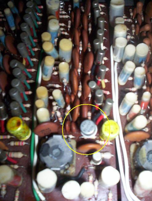
Soldered dangling red wire to pin 7 ground of the C oscillator plug. Here's a pic of that. Worked like a champ and got rid of the faint rumbling noise when the wire is disconnected. I can now see where the wire used to be soldered onto the round socket itself, where the board pin sets in which would be very easy to break off when removing the board. I made sure to solder it to the actual tab underneath the socket this time so this should not happen in the future.
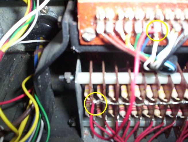
Dangling Red Wire: Solder to pin 7 Ground
1/13/2007
This afternoon I worked out the problem with the D# where it was missing 16' tone on the low D# key when cold. I've noticed this seems to be the most common tone to be missing. This could be just coincidence or perhaps there's something in the circuit where this footage sees a bit more voltage than the others. I may test that theory with a multimeter at some point. Anyhow, I nailed down which of the two divider transistors was bad by breathing on my fingers to heat them and then placing them gently around the transistor. When I did that, you could hear the 16' tone start working. Replaced that transistor with one of the replacements I got from vintage vibe. One tip here is not to be shocked if it doesn't work right away after replacing the transistor. Here it wasn't apparent the fix worked until I adjusted the bias pot to dial it in.
|
Warm fingers narrow down bad transistor |
Replaced bad transistor in lowest divider with Raytheon 322 |
1/15/2007
The main focus today was to start working on cleaning and leveling the keyboard. See photo array below. I found the white key caps came off quite easily but the black key caps were challenging and I think it would be very easy to break a key stop or some other part of the key mechanism by pulling too hard. Be careful when attempting this project. I found it best to use a heat gun and by just heating the key for a few seconds, they pull free rather easily. I think this softens the plastic and the old glue just enough so they break free.
I cleaned each key cap as I went along. There are two things that factor into the height of the key 1) The metal key stop that sits inside each metal key arm (see photo) 2) The rubber bushing that fits around the metal key stop. Tonight I found that someone had put a replacement rubber bushing on two of the keys which was causing them to sit too high. The bushings in the Continental are very similar to those in the Gibson G101 organ so I had some of those on hand from another project as I'm holding up in the photo. I found that the Continental keys sit best if I shave the replacement rubber bushings down a bit with a razor blade so they're not so thick. Once I did this, the keys sat level, with minor adjustment to the metal key stop required (by bending it up or down). Again, one needs to be careful when bending the key stops because the metal can break from fatigue and that would be a very difficult thing to fix.
I learned there is also a felt or foam pad that sits underneath the white and black keys which can absorb shock if the key bottoms all the way down. Seems a good project would be to replace this pad. I may do that depending on the condition I find that pad in as I move up the keyboard. For now, it looks OK on the bottom keys. I think it's possible that the pad could be worn on more frequently used keys. We will see as we go along! I am pleased with the results I see on the bottom octave where I have completely cleaned and leveled the keys.
Leveling keys required adjustment to the rubber bushings and key stops
1/16/2007
Continue to work on cleaning and leveling the keys. What I'm learning is that just about all the unevenness along the keyboard is due to worn out or missing rubber bushings. Am working on sourcing some more of those as I think it will be prudent to replace all of them. Some of the keys have a 'grinding' sort of feeling when depressed and I found this is due rubber bushings that have completly hardened and are breaking apart which rubs against the inside of the metal key lever. I have just a very few number of these rubber bushings on hand but I can tell the keys that have new bushings feel like brand new keys to me. So, I would advise anyone doing this key leveling to check out those rubber bushings. They can do all kinds of strange things with the action. One bushing had turned to mush and was causing the key to stick on it. Many are hard; some are breaking apart as I described.
One huge accomplishment today is that all the keys now sound normally even when the organ is cold. The transistor change outs I did on the E board seem to have done the trick. Have had no problems today with missing footages, warbling, or other common problems. The organ is set up in my garage which is currently about 20 degrees F, pretty cold.
Had one strange annomoly tonight when working on the organ. I went out to work on it and it would not power on. Checked the fuse, checked for shorts in the cable. Yes, it was plugged in. After rocking the power switch back and forth a few times, it powered on and I have not been able to repeat this problem yet. I had a Vox Supercontinental that wore out a power switch. What's strange is that also at the same time I had trouble with the vibrato switch not engaging the vibrato. Again, rocked it back and forth a few times and the problem went away. Weird that both rocker switches decided to go on the fritz at the same time. I'm wondering if I may have accidentally gotten some cleaning solution in the rockers when working on the keys? As a precaution, I'm going to change out both rocker switches so it is dependable and one less thing to worry about. Am keeping my eye out for a suitable replacement.
1/17/2007
Got the additional 100uf caps that I needed. So I spent the evening making sure each board had a new 100uf cap and bias pot. Special thanks to Richard Brinkerhoff for supplying me with some of the schematics for the Italian Continental. Here they are:
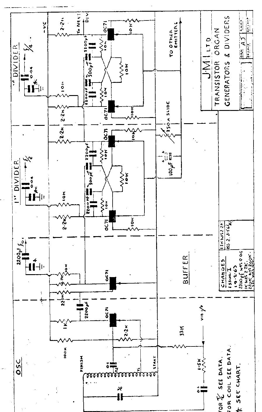
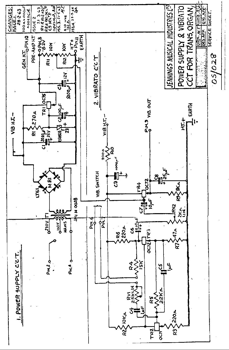
POWER SUPPLY & VIBRATO SCHEMATIC
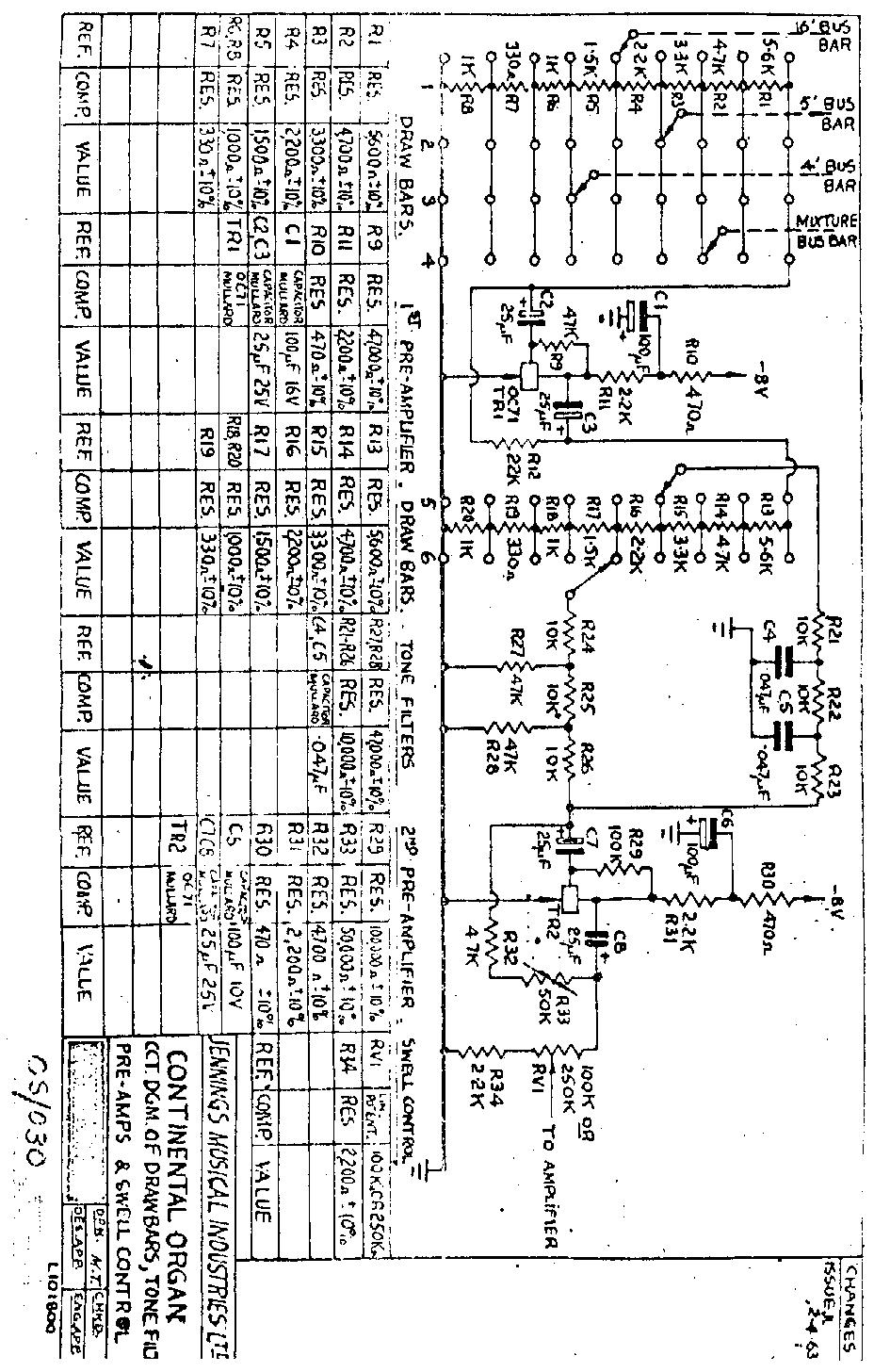
DRAWBAR/TONE FILTER/PRE AMP/SWELL CONTROL SCHEMATIC
1/18/2007
Placed an order with WD Greenhill for the replacement rubber bushings. I ordered a lot of 50. Special thanks to Cameron Penman for pointing out this source to get the rubber key stop bushings and other organ parts. Their website is www.wdgreenhill.com. I will post an exact part number here once I have that info
Cosmetic parts I ordered from Northcoast Music came today. This includes the organ lid latches, hinges, and handle. Will begin prepping the outside of the organ for the re-tolex job. Will start by removing the old tolex. Am going to attempt to salvage the metal piping and logos.
Glued and clamped all four corners of the top
1/19/2007
As part of the prep work for the retolex job, I went ahead and removed tolex around the two holes in the back panel of the organ where the cross braces screw on. As mentioned, the tee nuts that these cross braces fasten onto were missing on this organ and the holes the tee nuts go in were pretty disfigured. I filled those two holes with DAP Plastic Wood as seen in the photos below. This stuff is supposed to dry into a hard surface which I plan to drill out and mount the new tee nuts. I'll report back on how well this compound works. Have also been thinking of fashioning a thin sheet metal plate to go on the inside of this panel to give additional strength to the Tee Nuts.

Filled worn misshaped Tee Nut holes with DAP Plastic Wood
2/11/2007
Lots of the cosmetic work has been done since my last post.
Retolexing job: New black basketweave tolex has arrived! First step was to remove all of the old tolex. This was fairly easy. Most came off using just my hands to pull it off. There were a few spots which required the razor blade. Saved and reused the grey piping. This worked out well. The organ itself can be covered with three pieces. First piece is the largest piece which covers the back, bottom, and front. This is one long rectangular piece. Pay careful attention to the grooves for the piping while doing this job and leave a little extra tolex along the groove to push the piping into later. The next two large pieces of tolex are the sides. I used a heat gun to bend the tolex around the corners. One thing that helped was having my jaguar organ handy so I could see how the original pieces were bent at the corners. So this helped get a pretty original -pattern. I must admit that even with the heat gun, it can be a challenge to get those corners right. You can't overheat the tolex too much or it will melt. I ended up heating so the tolex is just flexible enough and then patiently pulling and forming it around the corner. Here's a photo of the organ with the new tolex and the new organ hardware.
Vox with tolex removed. Used plastic garbage bags to cover the electronics
Since moving the organ inside, a few new problems have cropped up with tone boards. I think working on the organ in the cold garage made it difficult to weed out transistors that are heat sensitive. The Ab needed a transistor replacement after I found it would warble when warm. It was a single transistor, (8th from the top of the board), that needed replacement. I had one of the ones I got from vintage vibe left over and it did the trick. Some transistors need replacement on the Bb as I now have to crank the bias pot all the way counter clockwise to get all the footages to sound and to my ear this makes the Bb just slightly louder than the other notes. It's barely noticeable but I can definitely tell that's happening. I suspect the lowest divider transistors so will go after those soon.
The keys have all been leveled, more or less. I didn't strive for perfection here but was able to get a good general leveling -- looks level to the naked eye. The rubber key stop bushings arrived from WD Greenhill and those worked nicely. There are little rubber ears on them which needed to be shaved off with a razor blade first, though. The action is now very smooth.
The problem I mentioned with the switches has not cropped up again but I have 10 new rockers switches (white actuator with black case) on hand now just for the occasion. Was able to locate these on ebay. I'm going to offer up some of my spare parts soon on this page, payable via paypal, if anyone needs 'em. I'll offer up some switches, bias pots, transistors, etc. Sort of a post-project garage sale.
There's really not much left to do. I need to mount the Continental Logo on the back of the organ and the serial number plate on the bottom. Other than that, all there is left to do is play it! Am going to play it often as to weed out any remaining transistors that may be sensitive to heat in order to make this organ as problem free as possible. One thing I have learned from working on this beast is that tinkering with it is going to be an ongoing process. There are 168 transistors, just on the tone boards alone. That's a lot of transistors to go bad. Some would say I should probably just wholesale replace all of them which I may do at some point for reliability. We'll see how it goes.
2/23/2007
Had a problem crop up with the A#. Had to turn the bias pot all the way counter clockwise in order to get all the footages to sound. This also made the A# notes slightly louder than all the other notes. I've acquired a lot of SFT 353 transistors. What a score! These look almost identical in appearance to the originals and they work perfectly. I went ahead and started replacing divider transistors in the A# board. Replaced them one pair at a time. The board now has 10 new SFT 353 transistors in it and works perfectly.
3/4/2007
Still combating temperature related issues as they come up. latest was my C# losing a footage & getting some warbling when the organ was moved back into the cold garage. All the other notes work perfect though. So this is definitely progress. I pinpointed the transistor that was temperature sensitive in the C# board and my first plan of attack was to find a good matching pair of the SFT 353 transistors and install them in that divider. Unfortunately, what I found is that the SFT353 do not mix well with the SFT 363 -- in other words, 12 363s did not work well with the 2 353s. I was able to dial in the footages with this replacement, however, it was only within a very tiny range of the bias pot so this would be problematic for reliability. What I ended up doing was finding 2 good working SFT 363s I had left over from the other board replacements and I went ahead and put those in the C# board. That did it. I think what I've discovered here is the SFT353 transistors work very well but only when replacing most or all of them. If you try and mix these with other types, they make it difficult to dial in the bias pot since they probably differ too much from the 363s. Just a theory at this point.
Also did some finishing work last night gluing down the new tolex. There were some spots along the edges where it wraps around the inside of the organ that were coming up. I used DAP rubber cement for gluing these edges and clamped it down. Worked well. I also have not yet put on the Continental logo. I have been thinking I could get some silk screening film at an art supply store and cut it carefully around the silver lettering with an exacto knife. This would leave the silver letters covered with the film and I could spray on a nice new coating of gloss black paint. Will post pictures if I attempt this. Seems like a neat idea.
3/9/2007
Tonight was the first "road test" for the organ. Took the organ out to jam at a friends house. For the first couple of hours, the organ performed flawlessly. However, right at the tail end of the jam, my C# started warbling and I lost 16' tone on the F. Turning off the organ and letting it cool for a few minutes fixed this problem. I am going to use the organ for a short gig this Friday (45 minute set) since I haven't had any problems with it unless it's on for an extended period of time. My plan after that gig, though, is to go ahead and retransistor the C# and F boards with the SFT353 transistors -- replace all divider transistors. I have already done this on the Bb and it works flawlessly with a complete changeout to the SFT353 transistors.
3/19/2007
Used the organ for the first time at a gig on Friday. No problems cropped up to report. I did have to be ultra careful not to damage the tolex on the back due to I don't have the metal glides yet. Have been doing some research and it looks like the most authentic replacement is actually called an upholstery nail. I found a nickel plated upholstery nail at a site online which looks like it will do the trick and they are only .80 each (minimum order of 10 pieces). I'll report back with a link to their url and an item number once they arrive and I have a chance to give 'em a try. The organ sound went over really well with the crowd we played for. VOX: it's what's happening!
4/5/2007
Here's a photo of the organ with better lighting:
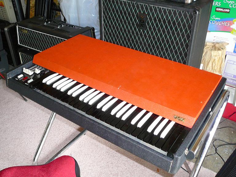
Vox Superbeatle and AC30 extension cab pictured in background
5/7/2007
Have been working on some minor issues with the organ. One issue is some of the tolex on the inside of the lid has been coming up so I glued it down with rubber cement and clamped it. What I've found is the spray glue works great for the majority of the project but the edges do require some rubber cement and clamping. Handle Screws: There are four screws total which hold on the handle. The two screws closest to the edge of the lid were pressing down on two keys when the lid was on the organ. I didn't know this until I had the organ plugged in, amp turned on, and I could hear the keys sound when I closed the lid. Oops! So I went ahead and replaced these with two shorter screws. This is definitely something to watch out for as I noticed the keys it was pressing down on were becoming uneven compared to the adjascent keys. Obviously the screws have been applying pressure to the metal key stop and bending it slightly. Glad I caught this before any real damage was done. The new screws just sit flush with the inside edge of the lid. I found a bad solder joint in the B tone board on one of my transistors so I reheated the solder and fixed that.
5/15/2007
Spent some time tonight doing some extra leveling of the keys and replacing a few more bad rubber key stop bushings that have cropped up. Since tacking down the loose transistor on the B board, I have had no further problems with it. As a side note, I've started work to recondition a 1954 Electrolux Model E Vacuum cleaner in case anyone is interested lol! I may post a picture just for fun once that project is completed. It's an amazingly simple device compared to the Continental Organ.
6/23/2007
Gigged with the organ this past Tuesday and it was really the first true road test since we played a 120 minute set. Strangely enough, the only problem that cropped up was when I first powered the organ on and checked the keys. The A#/Bb was missing most footages and sounded like I noted back on 2/23/06. Recall I had replaced 10 of the 12 divider transistors with the new SFT-353 type. I was able to easily get the organ playable for the gig by removing the orange top and turning the bias pot all the way counter-clockwise. Again, this made the A# notes slightly louder than the others but it was not perceptable from a musical performance perspective. After returning the organ to my home and going to power it on the next day I had to return the bias pot back to the prior position, about 8 O'Clock. I suspect temperature or humidity plays a factor with that board. There are still two non-SFT 353 transistors in the board which I may replace but I don't believe those are for the footages that go missing. Perhaps, though, having the two different type transistors is enough to throw off the bias at certain temperatures since they don't match well with the SFT-353 transistors...just a theory...but I have a whole bag of them so I might as well try it out. Will report back on how that goes. But other than this glitch to report, the organ was a stellar success at the gig.
10/9/2008
Had been having issues with C, C#, and D# keys in practice as well as F key above middle C sticking. These were pretty easy repairs. I replaced all divider transistors in the C and C# boards with the SFT-353 that I got from Bulgaria. Those boards are now rock solid. The D# turned out to be just a bad cold solder joint on one divider transistor which was an easy fix. The stickey F was also pretty easy. As with the rest of the stickey keys found earlier on in the project, this was an aged rubber key stop bushing. The bushing was dissintegrating and getting stickey with age. I replaced this with a new bushing and it works great. I can see that it will be smart to completely retransistor all of the boards. It takes me about 30-45 minutes per board, in between picking out the new transistors (which involves HFE testing with my multimeter), desoldering the old, and soldering in the new. This may not be totally necessary but what I typically do is HFE test a batch of transistors and pick 12 that are similar value. Then I pair them with values as close as possible. Again, this may be an overly conservative step but the theory is that the closer in HFE value the transistors are, then the easier it will be to dial in the bias pot to a value that works for all divider transistors. I will probably work on this replacement over time.
11/12/2008
SFT-322 transistors arrived from Bulgaria (ebay purchase). I used these transistors to make sure that each of the 12 oscillator boards had a new set. 10 of the boards got a set of these SFT-322 transistors. 2 of the boards already had new replacements so I did not bother with those. Since doing this, it has improved reliability even further. I did this job mainly to make the organ more reliable since if one of the oscillator transistors goes out, you lose the whole note accross all octaves. This could be disasterous at a gig. I would recommend this for anyone gigging with these instruments. It was a pretty easy job -- about 1 hour of work.